Why do I need special cables for VFDs
February 14, 2020
Choosing the right cable for your variable frequency drive is critical to the operation of your system and avoiding costly downtime. To better understand why special cables are necessary, we’ll take a look at both the immediate and long-term impact that improper cables and configurations can have on your equipment along with ways to minimize problems.
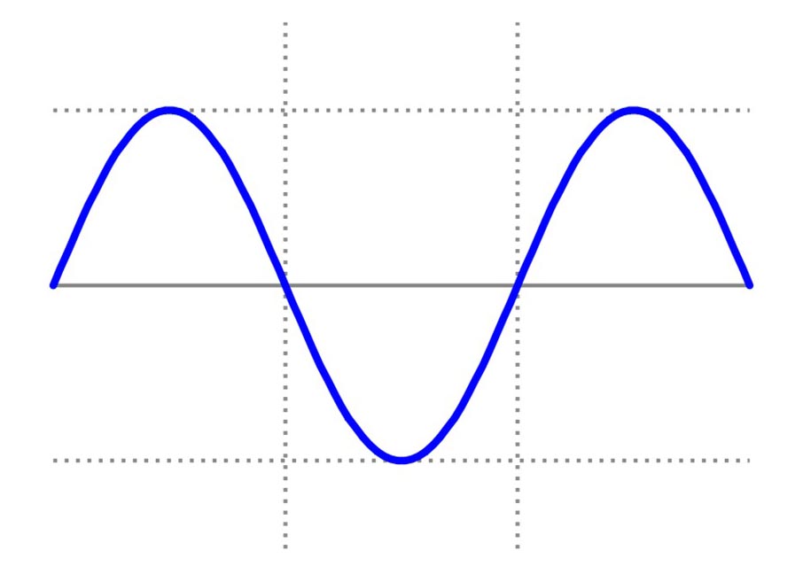
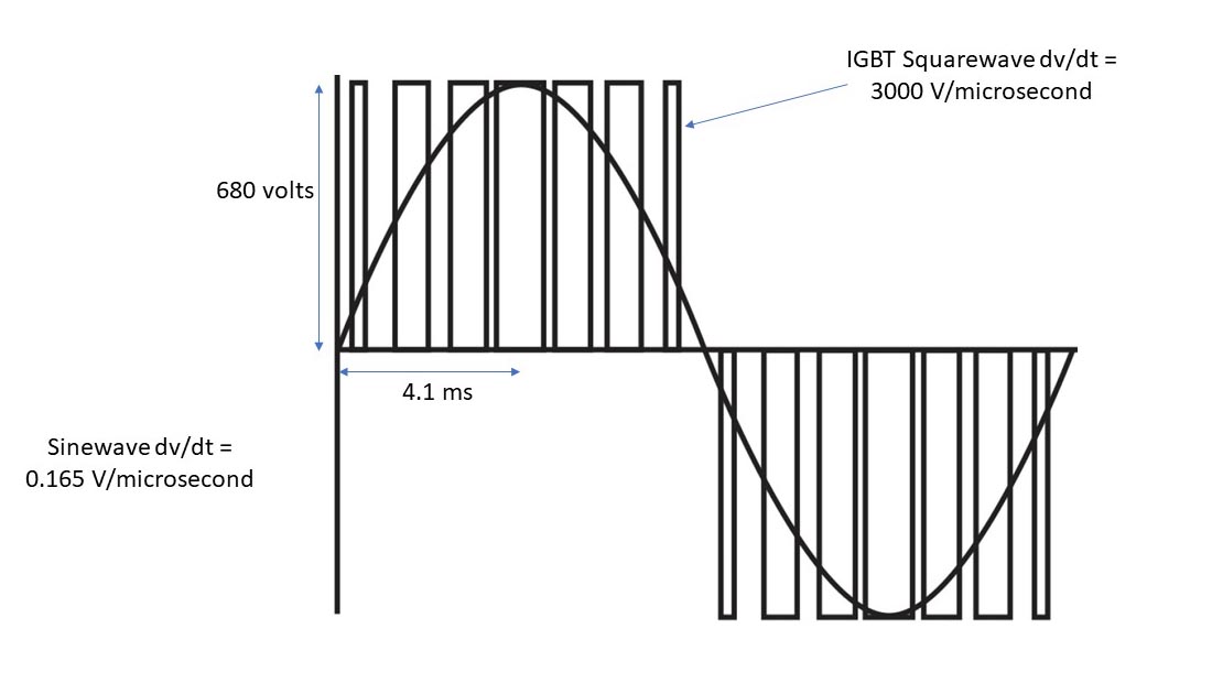
We will start by looking at the VFD output waveform. Unlike the utility grid sine save, which is generally quite smooth with low rise times, inverters attempt to recreate the sine wave by using a stream of square waves of varying pulse width. The fast-rising edges of these square waves place demands on the cable and motor and drove manufacturers to create what are called “VFD” cables.
On a 60 Hz utility grid, the voltage will go from zero volts to peak voltage in roughly 4 milliseconds. This produces a rise time (dv/dt) of less than 1 v per microsecond.
On the drive output, the voltage will go from zero volts to DC bus voltage in a microsecond. IGBT output devices typically switch at a rate of 1200 to 5000 times per cycle (depending on drive switching frequency settings).
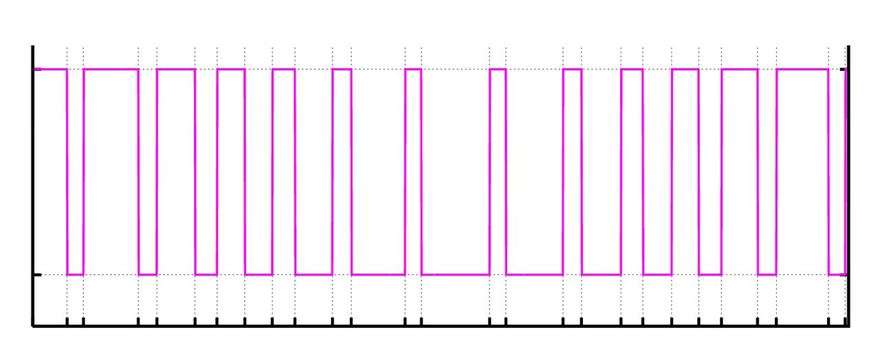
So, the waveforms between the input and output are substantially different and place different demands on power cables.
Let’s split the impacts from the waveform differences into two groups; immediate impacts and long-term impacts.
Immediate impacts include:
- Transmitted electrical noise (EMI/RFI) from the drive cables inducing voltages into other equipment (i.e., Low voltage signal cables, sensors, radios, etc.)
- Inverter tripping due to the capacitance of the cable.
The transmitted noise impact can be mitigated by using shielded cables and proper grounding techniques. This requires a full understanding of your facility’s grounding system and strict compliance to terminating the shields correctly (360-degree gland connectors, avoiding ground points along the cable length).
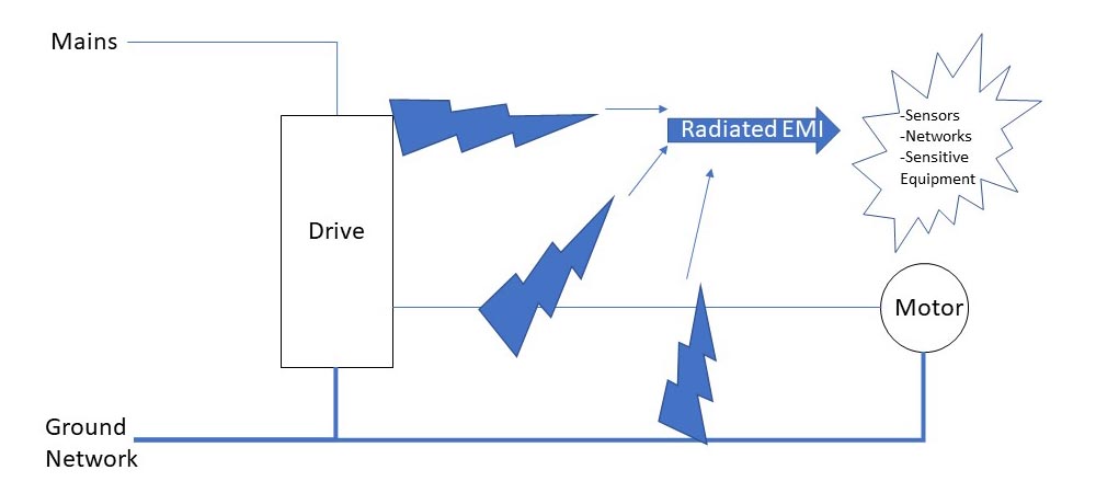
There are basically three approaches to shielding:
- Foil/mesh/drain wire shield configuration performs well for low and high frequency shielding (the mesh captures the lower frequency components and the foil captures the higher frequency components).
- Copper tape is less efficient at containing lower frequencies and can “gap” at bends, providing free space for the noise to exit.
- Armored cable provides excellent shielding over a wide bandwidth, but care must be taken to ensure that the armor is not grounded along its run to the motor.
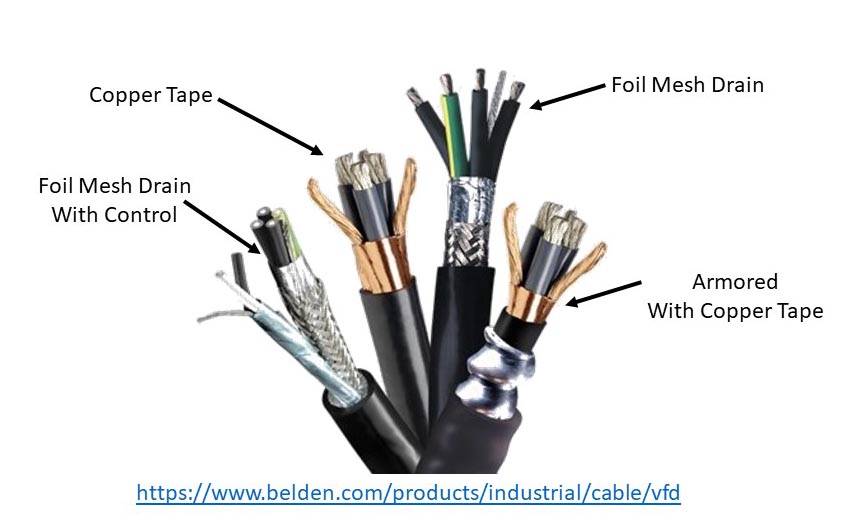
So, for noise containment the best choice would be armored cable, followed by foil/mesh/drain and copper tape.
I can’t emphasize enough how important it is to properly follow established grounding practices. If not followed, all you have is an expensive motor cable. ABB has published an excellent paper on the proper techniques for drives.
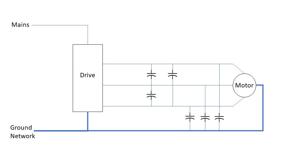
Now let’s discuss the potential for inverter tripping, or performing erratically, due to cables. When a charge is placed across two conductors separated by an insulator, a capacitance is created that is inversely proportional to the dielectric index of the insulating material. With motor cables in close proximity, the capacitance can range from 50 to 150 pf/ft, depending on the cables used. With long motor leads, say 100 feet, you can see a peak current of 1 to 1.5 amps just to charge and discharge this capacitor. With even longer leads, this current peak can get to a point where it interferes with the drives control calculations and in a worst-case scenario, the current can exceed the instantaneous overcurrent trip point of the drive.
To combat the cable capacitance charging currents, keep the drive as close as practical to the motor, use motor cables with >20 mil of XLPE insulation. As we will discuss in a moment, cables unitizing XPLE insulation have a lower capacitance and will reduce the charging currents. If your drive is already mounted, the only practical option is to install a filter at the drive to limit the rise time of the voltage.
So, in order to avoid the immediate effects from the drive waveform, the recommendation would be to locate the drive close to the motor and/or use a 1000v rated cable with a >20mil XLPE insulation and a foil/mesh/drain wire shield.
Now, let’s talk about the long term effects of the drive waveform.
Long term effects include:
- Motor Cable Degradation
- Motor Insulation Damage
- Motor Bearing Damage
The fast rise times of the output voltage that are applied to the cable result in transmission line reflections that can essentially double the voltage for short durations when the output switches. These spikes can exceed the corona inception voltage of the cable insulation. If air is present, ozone will be produced. Ozone will degrade PVC and can lead to a cable failure.
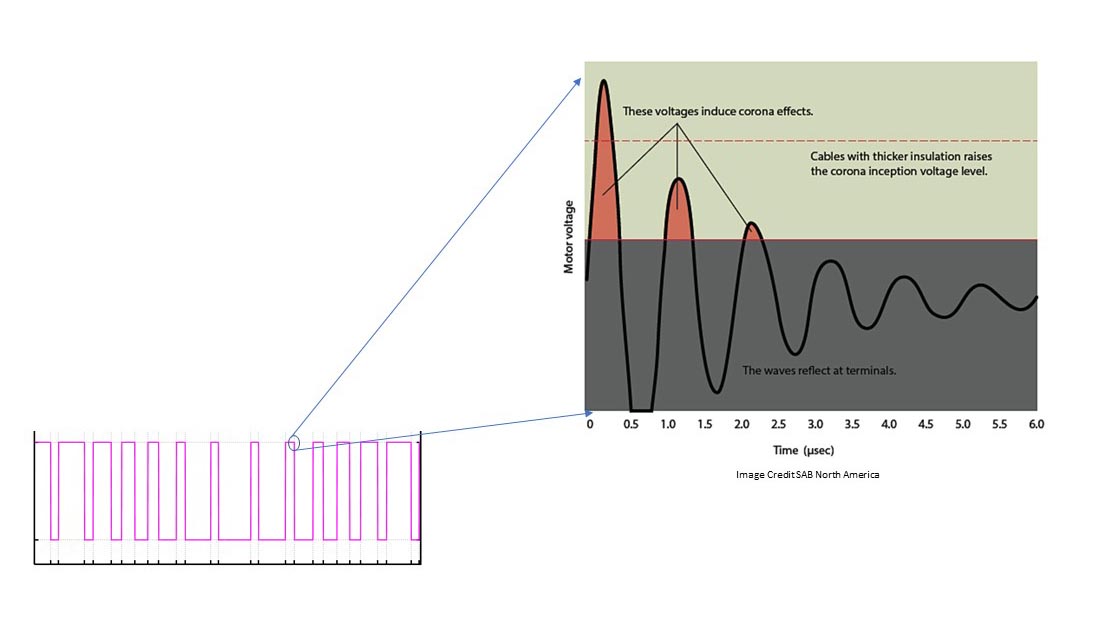
For this reason, most VFD manufacturers recommend using cable with XPLE insulation with a minimum 20mil thickness. XPLE has a higher corona inception voltage is not as likely to fail as a PVC insulated cable.
Motor insulation can also be damaged by these high voltage spikes. While XPLE cables have a lower capacitance, which can influence transmission line effects, if you have a motor with insulation failures, you will probably need a filter at the drive or a terminator at the motor. It is worth noting that most new motors that are inverter rated have improved insulation that essentially eliminates insulation failure due to these voltage spikes.
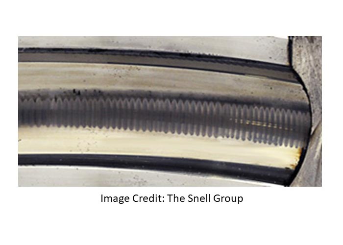
Bearing currents can result in pitting of the bearing race and over time, failure of the bearing. There are many pictures of this phenomena, called fluting, available online. Over the years, I have experienced more issues with bearing currents than motor insulation failures.
A large portion of bearing current is caused by transient common-mode voltages generated by the switching of the drive output devices. The key to minimizing these voltages is to keep the ground potential at the drive at the same ground potential at the motors. In other words, keep the impedance of the ground system as low as possible.
For VFD ground conductors, there is not a clear standard from drive manufacturers. Some manufacturers specify segmented grounds and others specify full-sized ground conductors.
Cables with segmented grounds are sometimes referred to as symmetrical or balanced cables. As shown, segmented cables include 3 ground wires and three main conductors, all wound together in a manner that promotes coupling of high frequencies to ground and minimized common-mode voltage. Segmented grounds will provide the best performance with regard to common-mode voltage suppression.
The chart below provides an overview of cable configurations and performance.
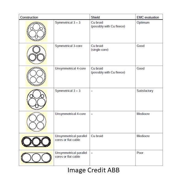
So, my take away is that the best technical choice would be to use armored, symmetrical XPLE cable, followed by shielded symmetrical XPLE cable. Let’s take a look at the cost benefit of each choice.
As you can see, the cost difference between “adequate” and optimal is roughly 3x
Here are some common rules to keep in mind that will help minimize issues:
- Minimize the length of exposed cable after the jacket is removed.
- Ground shields, drain wires and ground leads at both the drive and motor.
- Do not ground the cable at intermediate points along the run.
- Avoid long parallel control/sensor and motor lead runs.
- If control/sensor cables cross motor cables, do so at a 90-degree angle.
- Use a conductive gland at the motor to provide 360-degree shield grounding.
To wrap up, care must be taken in selecting VFD cables. Immediate impacts from electrical noise interference can be economically managed with the selection of XLPE foil/mesh shielded cable and proper wire dressing. Longer-term impacts are much more expensive to mitigate as they typically result in downtimes from potential replacement of cables and motor repairs. This is where symmetrical XLPE cables can provide benefits. Ultimately, real-world constraints such as cable length and budgets can limit the designer’s options.
I hope this short explanation provides you with a better understanding of the basic characteristics of VFD cables and how they can impact your system performance.
Remember, work safe, lockout and tag out.


