Case Study:
Faulty Heat/Cool Loops on Extruder Barrel
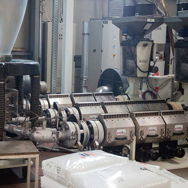
One zone required constant cooling due to the amount of process heat being generated.
Objective
- Resolve a zone requiring constant cooling due to process heat being generated.
Solutions
- Change PIDE instruction to use velocity for the algorithm to produce adaptive gains allowing changes in gains in a running loop.
- Improve output resolution by setting the SRTP instruction and cooling valve logic to a much faster periodic task than the PIDE instruction.
- Increased cooling max pulse time to allow for higher resolution and allow the PID to work by letting the output integrate higher.
- Properly step-tuned each zone on both the heat and cool side.
Results and Benefits
- The PID can integrate to around negative 70% and hold the zone stable within +/- 1 degree.
- The PID can now come back into control successfully following an upset.

Background
A customer was experiencing difficulty controlling the heat and cool loops on an extruder barrel. These zones sometimes control around zero on the PID output, which can cause an oscillation with the output swinging from heat to cool. Tuning the PID or heat and cool settings can temporarily cause the problem to settle, but an upset will send it back into oscillation.
Due to a similar issue on another recent job, we suspected four potential causes for this problem. First, the standard PID instruction uses a positional for an algorithm that works on errors directly. The problem occurs when crossing over to zero when moving from heat to cool (and vice versa), leading to a change in the gains and causing a step in the output. This step inputs a heat or cool response that’s unnecessary and can cause the loop to be unstable and difficult to tune.
The second cause could be poor output resolution resulting because the output resolution is a function of the CycleTime of the SRTP and how of then the SRTP executes. For example, if a CycleTime for the SRTP is defined for ten seconds and the SRTP is executed in the same periodic task as the PID at one second, the output resolution would only be ten percent.
A third possibility is the cooling pulse max time set at 60 seconds or below, or, in some cases, as low as the 15 to 30-second range. The result is poor resolution for the PID output and an integral gain that is very low. Lastly, poor PID tuning can cause these problems as tuning parameters from previous or similar setups are often used rather than properly step-tuned for each zone.
Quad Plus Solution
We worked to resolve each of these potential issues, starting with the PIDE instruction. The enhanced instruction uses a velocity form algorithm that works on a change in error to provide adaptive gains, thus allowing changes in gains in a running loop to eliminate the step in output when crossing zero and changing from heat to cool gains.
Next, the SRTP instruction and the cooling valve logic (timer calculation and actual OTE for the solenoid) had to be in a much faster periodic task than the PIDE instruction. Then, the cooling max pulse time was increased. We found that 300 seconds worked well for most zones, and 200 seconds worked well for a troublesome zone that was constantly on the cooling side of the output. The result was a higher resolution, which allows the PID to work by letting the output integrate higher. Lastly, we thoroughly step-tuned each zone, both on the heat and cool sides.
We’ll Get to the Bottom of Tricky Problems
Sometimes, equipment failures, errors, or breakdowns have a clear source. Other times, it can be caused by a complex interaction between different areas of your line, and even the slightest imbalance can cause big problems.
The Quad Plus team has the knowledge and experience to get to the bottom of mysterious failures and deliver comprehensive solutions that address all sides of your problems.


